My Solution
Hardware:
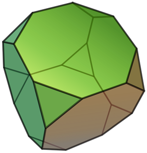 First of all I would like to present the ‘truncated cube’, in case you don’t know him!
The nice thing about the truncated cube is that however you look at it you can always see at least 4 of its faces. For pose estimation of a 3D object you kind of need to see 4 non-coplanar points at all times, so if we were to put markers on each face of a truncated cube this is could be a perfect match for our purpose. Fortunately it doesn’t have to be a completely uniform polyhedron; a truncated cuboid also shares this characteristic. Another good thing about this type of polyhedra is that its shape can easily become the base of a HMD shell design.
Marker Integration:
The next problem that we have is that for pose estimation we not only need to ‘see’ the markers but we need to be able to identify them, as in put a number to each marker and be able to tell which one is which.
Infrared (IR) markers are popular because they are very easy to discriminate from the background with proper filters, but being able to detect several colors can help to simplify the problem a lot. Colors on the visible spectrum are obviously harder to detect than IR but we have something that we can use in our advantage — since we are integrating these markers on a HMD we can actually control the background where the colors are displayed to make blob detection easier.
Here are some of my first experiments, where I decided to use simple color stickers on the darkest background possible. For that I used flocking paper found in telescopes, which is more practical and uniform than using black velvet for instance. I’m using a PlayStation Eye as the main camera for image processing.
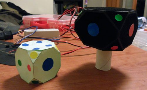
With this setup I managed to get pretty good results; it was good enough to build the main blob analysis algorithm and I was able to discriminate four basic colors (red, green, blue, yellow). As expected, the problem was that the result was very dependent on ambient light, small changes would make the recognition fail. The obvious next step was moving to color LEDs.
Looking back, finding the right LEDs to use was one of the biggest unexpected difficulties; they need to have a wide angle and display uniform light, and I had to test quite a few with different current intensities and camera settings until I found ones that performed well enough.
I also found out that I had to reduce the camera gain and exposure almost to the minimum settings possible in order to get correct colors (not white overexposure), this in turn helped to reduce blob ‘trails’ in fast movements and also had another desirable effect: since the whole image is darkened, blob-detection is already half-solved because only bright lights stand out. This actually makes the flocking dark paper quite unnecessary, but I decided to leave it anyway. Here I made a silly mistake though: I made all these tests with the camera running at 30 FPS instead of 60, and later I realized this really affects the color detection.
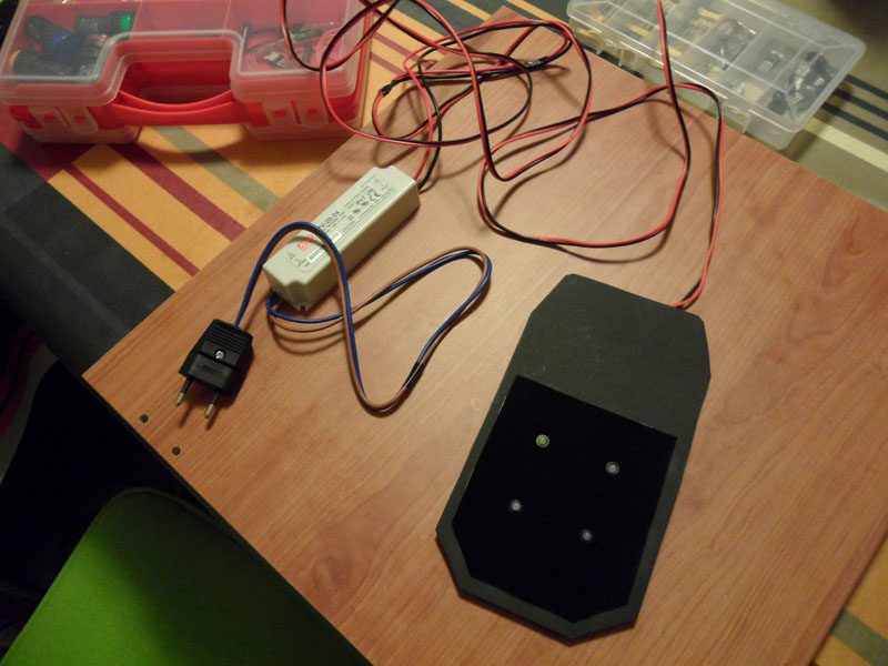
Here you can see the power source I used and one of the tests I made with LEDs:
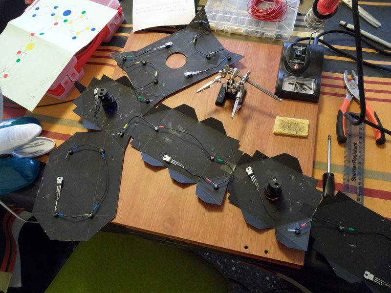
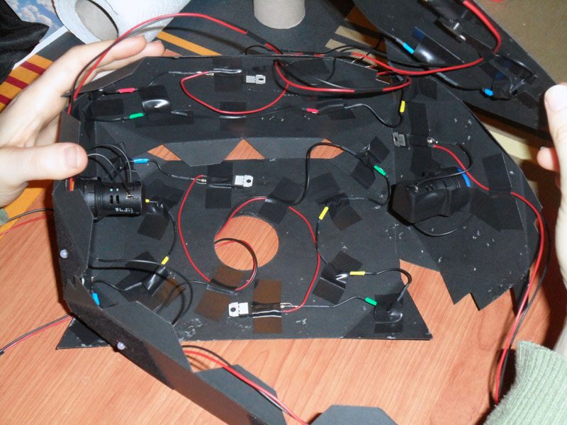
Once I was happy with the LEDs I found it was time to build the main prototype. In theory, we need to have only one marker per side of the truncated cuboid (16), this way we always have a minimum 4 non-coplanar points visible (and most of the time redundancy which is not bad). In practice though, this cuboid has to be split in 2 parts (front and back of the HMD). I thought that on the sides and top it would be better to have LEDs on both parts, even if they shared the same theorical plane. This is necessary to overcome occlusion by the head/neck itself.
Even though it wasn’t strictly necessary I decided to use some pilot lights for the front and the back in order to have two more different types of markers that would help with the point detection. I also decided to put two LEDs on the top and bottom of each part so we could detect at least four when looking straight from the top/bottom, without depending on the other part of the HMD. Later I regretted these decisions though, since they complicate the design, the detection algorithm, and actually create more problems than benefits.
Another mistake I made in retrospect was to fix the intensity of the LEDs using voltage regulators LM317 in combination with fixed resistors… I should have used potentiometers instead, in order to be able to vary the intensity of the LEDs without having to redo any soldering… oh well.
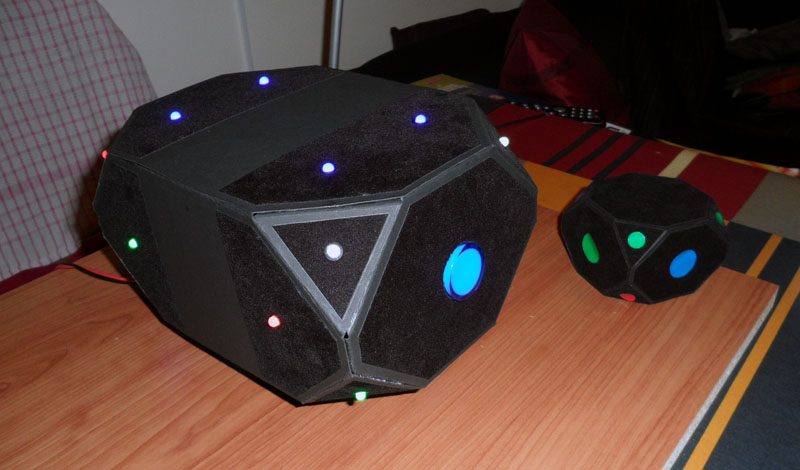
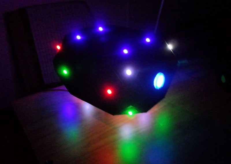
In the end my final design contained 22 individual markers of six different types: red, green, blue, white, Blue pilot, Yellow pilot.
Obviously in order to detect correctly the 22 different markers it would be ideal if we could have 22 different colors, but that is really not practical and I would dare say not possible, at least with the PlayStation Eye hardware. However having 4 or 6 different types of markers is enough for point detection if you distribute them more or less cleverly and take into account the surrounding markers while trying to identify an individual one. The LEDs don’t have to be on the exact positions I used or same colors, you can get creative with this. The only two rules are always four non-coplanar points visible and colored in a way it’s possible to match them with the complete 3d model.
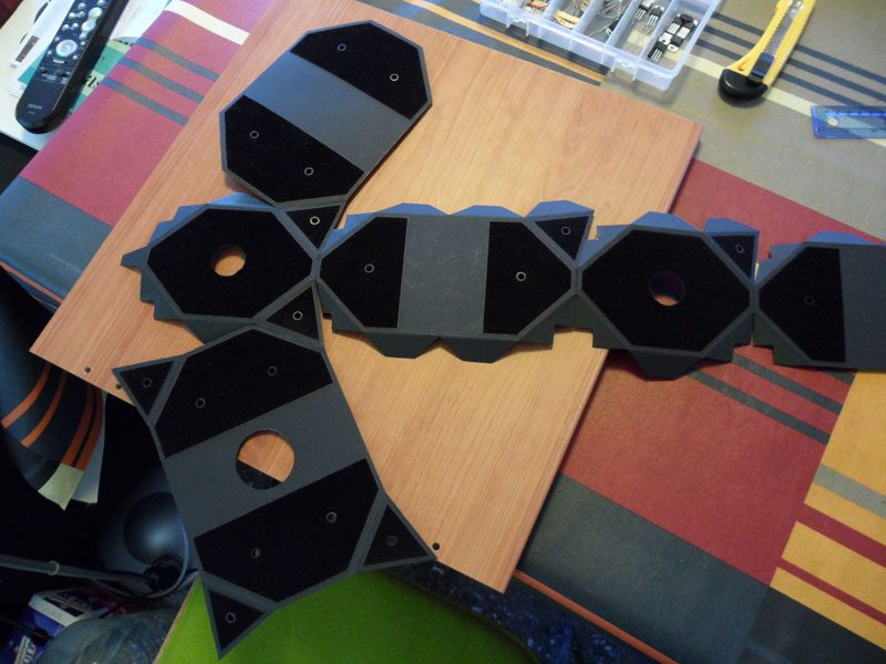
Pictures of the Build:
DIY Rough Cost Estimate:
- 20x LEDs -> 15$
- 2x pilot lights -> 8$
- 1x PS camera -> 15$
- LM317Ts, resistors, wires, etc -> 5$ aprox
- TOTAL aprox cost -> 43$
Bulk buying the components could be reduce cost greatly, probably under 12$ if you don’t count the camera. If DIYing you may need to add an AC/DC power supply (aprox 15$), which of course is not necessary if it’s integrated with the existing HMD power supply.
Here are images of the finished prototype:
 Third Parties")


