Capturing stereoscopic panoramas
Monoscopic panoramas (where both eyes see the same view) are straightforward to capture, and generally reproduce the original view reliably with no noticeable artifacts. Other than not supporting any kind of parallax or positional tracking, they are correct. Stereoscopic panoramas, in which the left and right eye see different images, are a different beast: there is no known way of reproducing them that is both correct and practical.
One strategy for doing stereoscopic panoramas is to place a large number of cameras on the surface of a sphere, maybe a few hundred cameras on a sphere the size of a beachball, and store and compress all of these captured camera views. During viewing, light field techniques can be used to synthesize any camera view at any orientation and any position located inside the sphere. This allows us to generate correct stereoscopic results regardless of viewing angle and even support limited positional tracking, but at a tremendous cost: even with compression, a typical full-resolution light field image may be over 500 MB in size. And that’s just a single image; video is out of the question. More effective compression techniques exist but remain difficult to decompress in real-time.
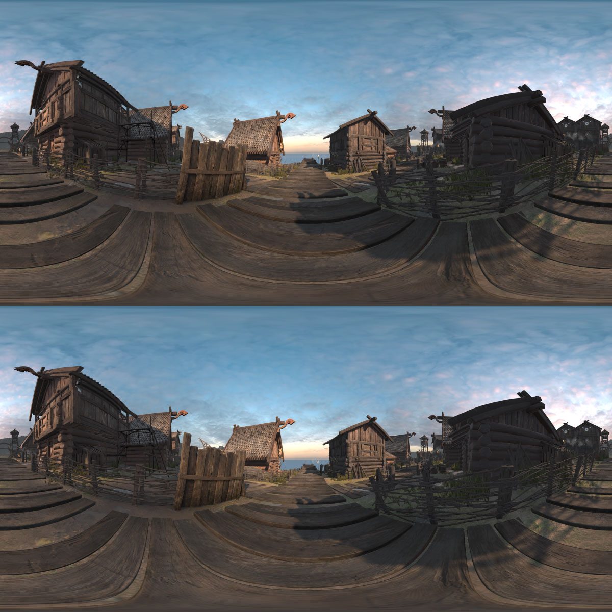
So, rather than trying to be totally correct, we use an alternate approach based on the equirectangular projection used for monoscopic images above. Instead of having one image, we have two: one for the left eye (on top) and one for the right eye (on bottom), as shown below. The viewer remains efficient and simple to implement: both views are applied as textures to a large sphere surrounding the viewer, with the left eye seeing only the left view texture, and the right eye seeing only the right view texture (using camera layers).
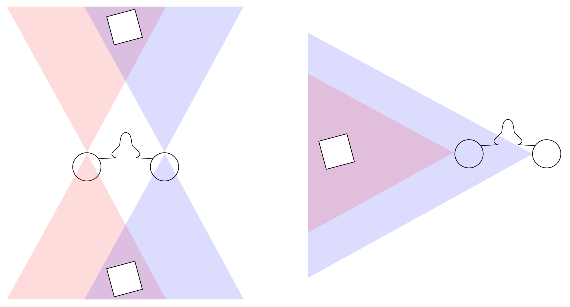
The simplest possible way to generate this image would be to put down two cameras at fixed positions, separated by the average distance between a person’s eyes, and then capture a monoscopic 360 degree panorama for each one. This will result in roughly correct results for the area directly in front of the viewer, but when looking behind them, left and right will be reversed, and when looking in any other direction results will also be incorrect, as the diagram below shows.
The simplest way to fix this, and the one most commonly used, is to divide the equirectangular image into thin vertical strips, and render each of them separately. Each strip is rendered with both eyes looking directly toward that strip, greatly improving the stereoscopic effect.
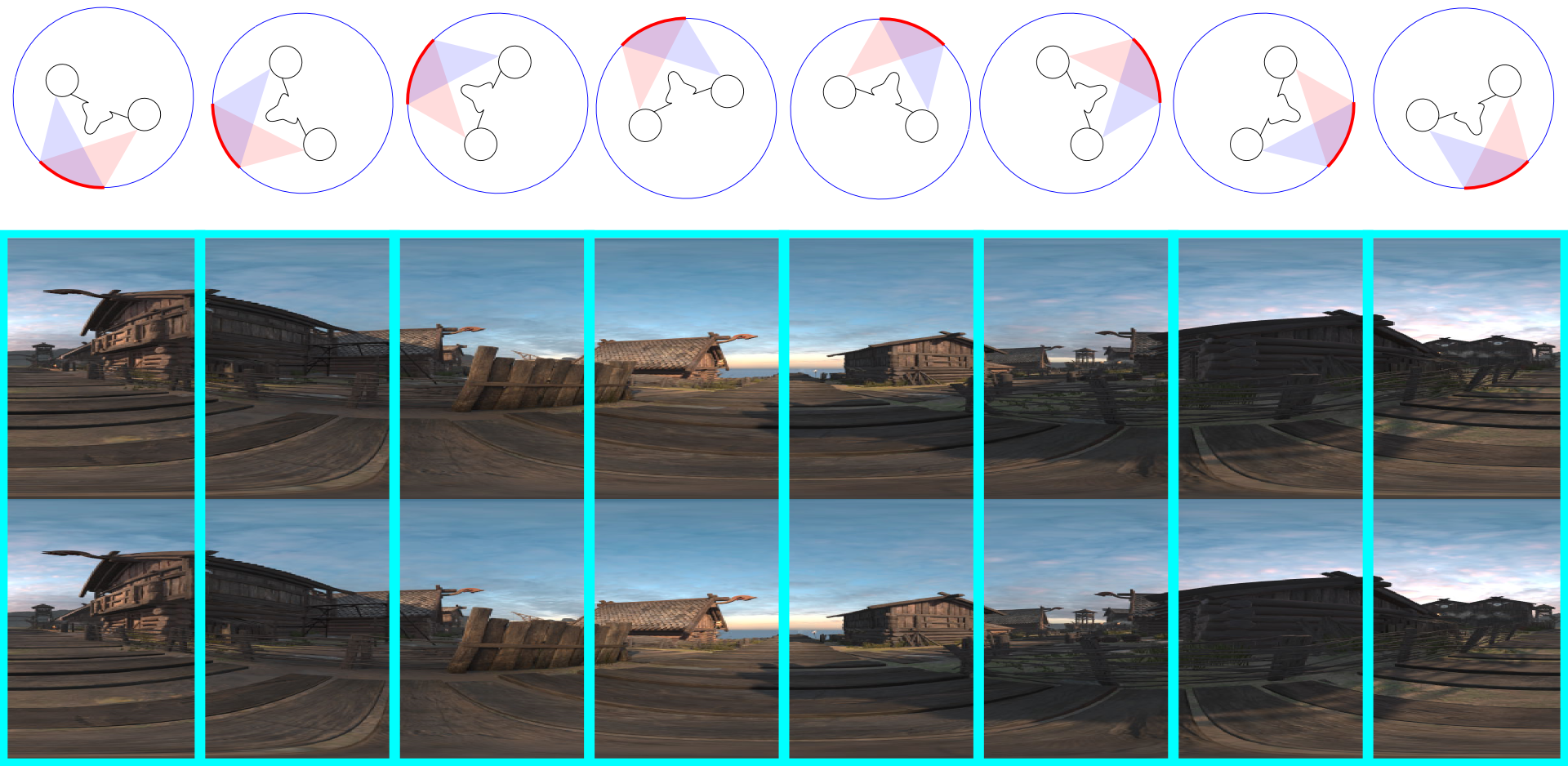
Provided the strips are thin and numerous enough, the seams between them will generally not be visible. Because the strips have limited horizontal field of view, they can also be rendered efficiently.
However, while this scheme works great for just turning your head left and right, it produces strange problems when looking up and down. If you look straight up, you are seeing all the strips simultaneously, coming together in a point at the poles, and only one of them is correct. Some are completely reversed. This will typically manifest as an inability to converge properly when looking toward the top and bottom poles.
In engines based on raytracing, such as OTOY’s Octane, they successfully mitigate this problem by adjusting the distance between the eyes (IPD) based on how far you look up or down. At the equator (no looking up or down), the IPD is at its maximum value. At the poles, IPD is reduced to zero, eliminating any stereo effect. In-between, it has intermediate values and reduced stereo effect. Because stereo effect is minimal when looking straight up or down, the errors in the stereo, although still present, are much less visually jarring.
Can a similar technique be used in a real-time engine like Unity? The answer is yes, and it works by bringing in ideas from light-field rendering and the Google Jump camera. We create a small circle with diameter equal to the distance between the eyes, and around the perimeter place a large number of virtual cameras (at least 8, typically 100). Each virtual camera has a massive field of view: over 180 degrees both horizontal and vertical. Because Unity cannot render with such a large field of view, each virtual camera is represented by a sub-array of four cameras each with about a 90 degree field of view. The four cameras are turned 45 degrees left, 45 degrees right, 45 degrees up, and 45 degrees down, and together cover all the field of view that we require.
Next: each pixel of the output is associated with two angles, the yaw or longitude (how far we must turn left/right to see that point), and the pitch or latitude (how far we must look up/down to see that point). The yaw is used to rotate the eyes to both look directly toward the point, just as with the vertical slices method. But now, the pitch is also used to scale the distance between the eyes. As a result, the eyes may lie on the perimeter of the circle, or may lie anywhere inside the circle.
To render a pixel, the two eyes each cast rays toward the circle. When they hit the circle, they hit it between two of the virtual cameras. We continue casting the rays out from those two virtual cameras to determine the correct color for the pixel from each of the two viewpoints. Finally, we blend the two resulting colors together based on the distance to each camera.
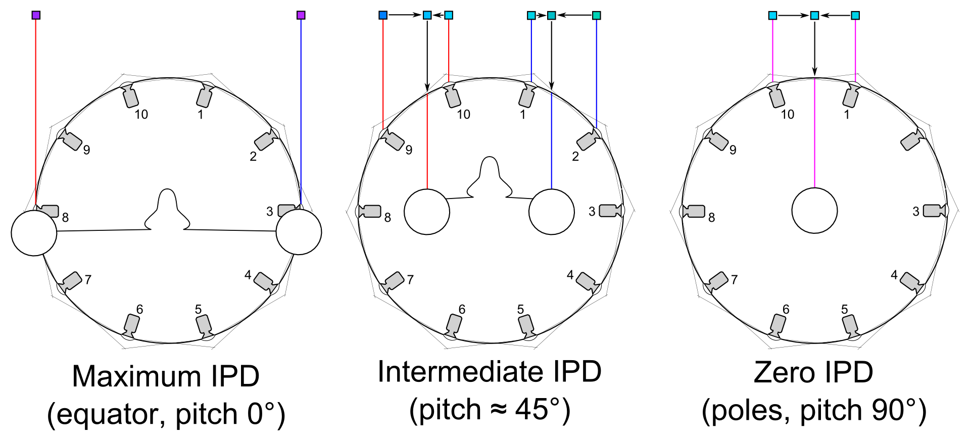
In the example above, we have 10 virtual cameras, each with a 216 degree field of view (each camera view is actually captured using four cameras with a 108 degree field of view). Three cases are shown:
- When pitch is zero (not looking up or down), the eyes lie on the perimeter of the circle, and their location on the circle determines which cameras to use. In the diagram, the left eye uses camera 8 and the right eye uses camera 3; at different yaw/longitude values different cameras would be used. The rays are sideways relative to the camera, which is okay because the cameras still have a wide enough angle of view to capture them.
- When pitch is intermediate, the eyes lie inside the circle. In the diagram, the pixel seen by the left eye is formed by combining a pixel from camera 9’s view and a pixel from camera 10’s view (camera 10’s pixel value has more influence because the ray from the left eye strikes the circle closer to camera 10 than to camera 9). Similar for right eye.
- When looking straight up or down, the eyes are both in the circle center. They both fire the same ray and receive the same pixel color.
Although this scheme is effective in reducing artifacts near the poles, it can still produce artifacts if not enough cameras are used, particularly if there are very close objects. These objects will appear to be blurry or doubled. This occurs because the camera rays are striking the object at a slightly different location than the eye ray. Fortunately, in a real-time rendered environment, rendering large numbers of camera views is fast. Because there is not enough memory to store all these views at once, usually just a few (usually 3 wide-angle virtual cameras) will be rendered at a time, and these will be used to render a portion of the final view.
There is some subtlety to how IPD should shrink as you move toward the poles. A simple linear function will result in a visible “crease” near the equator. A good IPD scaling function should be continuous at the equator, while also producing acceptable visual results at all pitch values. This is a somewhat empirical, ad-hoc process.


