Positional tracking is very important towards achieving immersion and presence in virtual reality. There are many ways to achieve positional tracking, with pros and cons for each solution. This article presents an overview of positional tracking technologies which could be used for virtual reality.
This guest article is written by Yuval Boger, CEO of Sensics, a Maryland-based company specializing in professional-level head mounted displays since 2003. Boger also blogs about VR on his personal blog, VRguy.net.
See Also: An Introduction to Positional Tracking and Degrees of Freedom (DOF)
Whether it is the head, arms, fingers, or objects (such as a weapon), positional tracking can deliver multiple benefits:
- Change the viewpoint of the user to reflect actions such as jumping, ducking or leaning forward.
- Show hands and other objects in the displayed image. A common complaint of users in virtual reality is that they can’t see their hands.
- Connect the physical and virtual world. For instance, by detecting hand position, a software program can implement the option to move virtual objects by touching them.
- Detect gestures. By analyzing position over time, a gesture can be detected. For instance, a user might draw the number “8” in air and have the software detect it.
There are several methods of tracking position and I felt it is worthwhile to describe some of them. This post focuses on tracking for virtual reality applications, so we will not look at tracking better focused for other uses. In no particular order, here are some of the popular tracking methods:
Magnetic Tracking
Magnetic tracking relies on measuring the intensity of the magnetic field in various directions. There is typically a base station that generates AC, DC, or pulsed DC excitation. As the distance between the measurement point and base station increases, the strength of the magnetic field decreases. If the measurement point is rotated, the distribution of the magnetic field is changed across the various axes, allowing determination of the orientation as well. Magnetic tracking has been implemented in several products, such as the Razer Hydra.
Magnetic tracking accuracy can be good in controlled environments (the Hydra specs are 1 mm positional accuracy and 1 degree rotational accuracy) but magnetic tracking is subject to interference from conductive materials near emitter or sensor, from magnetic fields generated by other electronic devices and from ferromagnetic materials in the tracking volume.
Acoustic Tracking
Acoustic tracking measures the time it takes a known acoustic signal to reach known receivers. Typically, multiple transmitters are distributed in the tracked environment and multiple receivers (microphones) are placed on tracked objects. If the receivers are aware when the signal was sent, the time to receive the signal can provide the distance from the transmitter. When multiple receivers/microphone are present in a known position on a rigid object, the time difference between them can provide data about the orientation of that rigid object relative to the transmitters. Acoustic tracking solutions were successfully implemented by companies such as Intersense.
Acoustic trackers require time-consuming calibration, are susceptible to measurement error as a result of ambient noise and often do not provide very high update rates. Often, acoustic tracking technologies are used in conjunction with other sensors, such as inertial sensors, and the resultant “sensor fusion” provides better accuracy than when just using the acoustic sensors.
Inertial Tracking
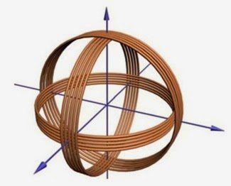
Inertial tracking uses accelerometers and gyroscopes. Accelerometers measure linear acceleration. Since the derivative of position with respect to time is velocity and the derivative of velocity is acceleration, the output of the accelerometer can be integrated to find the velocity and then integrated again to find the position (more precisely, the position relative to some initial point)
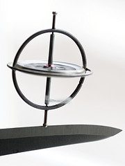
Gyroscopes to measure angular velocity. Gyroscopes are solid-state components based on MEMS technology, but have the same operating principle as the mechanical gyro shown on the right. Just like in the case of the accelerometer, the angular velocity can be integrated to determine angular position (more precisely, the angular position relative to the initial point).
The advantage of inertial tracking is that it is very inexpensive, can provide high update rates and low latency. However, the integration and double-integration lead to significant drift, especially as it relates to position information and thus it is hard to rely on inertial tracking to determine position.
Optical Tracking
There are several methods of optical tracking, all using various cameras to obtain positional information:
Optical Tracking With Markers
In this approach, an object is fitted with markers that form a well-known pattern. A video camera or multiple video cameras constantly seek the markers and then use various algorithms such as the POSIT algorithm to extract the position of the object from the markers. The algorithm matches the known marker position against what is being detected from the cameras and makes a determination on position and orientation. There is certainly some science to the number, location and arrangement of the markers. For instance, if we simply chose four markers that constitute the corners of a square, there would have been no way to determine if the object is positioned straight, is upside down or is rotated 90 degrees sideways. Such algorithms have to also contend with missing data in case one or more of the markers is outside the camera view or is temporarily obstructed.

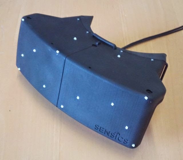
Markers can be passive or active. Active markers are typically IR lights that periodically flash. By synchronizing the time that they are on with the camera, it is easier to block out other IR lights in the tracking area. Passive markers are retro-reflectors, reflecting the IR light back towards the light source. In the case if passive markers, the camera is equipped with an IR flash which is reflected off the markers. The picture on the right, for instance, shows such camera with built-in IR lighting. The choice of active markers vs passive markers depends on many variables such as distance, type of surface, required viewing direction and more.
Different objects can be tracked at the same time if they have different marker arrangements.
Optical Tracking with Visible Markers
Another variation of optical tracking is tracking visible markers which are predefined patterns such as the one on the right (part of an Intersense optical tracking system). The camera can recognize the existence of this marker and if multiple markers are placed in known positions, the position and orientation can be calculated.
The markers can take various shapes and sizes. Sometimes, they look more like QR codes. Sometimes, they are circular as in this example. The key is to be able to create markers that would be quickly identified by the cameras in a computationally-efficient manner as well as be able to create a sufficiently large number of distinct markers.
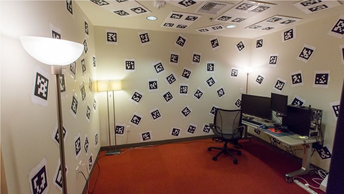 A famous example of “markers gone wild” is the demonstration room at Valve Software (see image below). The walls and ceiling were covered with various markers. A prototype HMD was equipped with cameras that continuously sought the various markers. Such marker arrangement, while often not practical, gave accurate positional tracking within the confines of the room.
Marker-less Tracking
If the geometry of the object is known (such as from a CAD model), it is possible to perform markerless tracking which continuously searches and compares the image with the known 3D model. For instance, such algorithm is being used below to track a box and then augment it with virtual objects. In this particular example, the object might be recognized by analyzing the real-time image for edges or color transitions and then matching these edges with the known model.
Even if the 3D model is not known, it might be possible to recognize more generic features of an object—such as a face or a body—and use them for continuous tracking, such as the video below
Tracking Using Depth Map
Another method to achieve tracking is with a depth map camera. A depth map camera, like the Kinect from Microsoft or the DS325 from SoftKinetic use various technologies (structured light, time of flight) to create a real-time map of the distances of the objects from the camera. Tracking can then be performed by attempting to extract the object to be tracked (hand, face, etc.) from the depth map and then analyze the extracted portion.
Sensor Fusion
Often, a combination of various tracking technologies can yield better results than using each one in isolation. For instance, let’s assume that optical tracking and inertial tracking are available. Inertial tracking develops drift but optical tracking is susceptible to occlusion (markers being hidden). If we combine both of them, we can get some useful benefits such as:
- If markers are occluded, we can use the data from the inertial tracker to estimate position until optical tracking is locked on the target again.
- Even if optical tracking is locked, if we have an inertial sensor that provides updates at a higher rate, we can use these updates in between the optical tracking reports to provide higher frequency updates for the positional tracking.
How to choose the best method?
There is no one right answer for the best tracking method. There are many factors to weigh:
- Tracking accuracy required
- Refresh rate required
- Whether the objects to be tracked are well know or can change from time to time
- Whether the objects to be tracked are rigid or flexible
- The desired tracking area
- Whether tracking needs to be indoor or also outdoor, where lighting conditions might be more challenging
- Cost, power consumption and computational power available for tracking


